SOLLICH 2003 SOK
Cathodic Protection Station for fuel tank. Imax=1A

Cathodic Protection Station with low power consumption, dedicated to systems operating in a wide range of ambient temperatures.

Application for cathodic protection:

various types of pipelines
steel structures
tanks of liquid and gaseous fuels

Microprocessor controlled.

All available operating modes and functions.

Supply: 12-24Vdc

RS 485 communication interface. Modbus RTU.

PRICE DEPENDS ON PRODUCT CONFIGURATION.
FOR PRODUCT QUOTE, PLEASE CONTACT THE MANUFACTURER.

SKU: 0-2-1 Categories: ,

Documentation

and technical data

Description

The SOLLICH 2003 CATHODIC PROTECTION STATION is designed for cathodic protection of metal structures built on a large area, on its surface, in the ground, water, with very good insulation in relation to the ground. In particular, these are all types of liquid and gas fuel tanks, pipelines and gas pipelines.

The Cathodic Protection Station works in a three-electrode system with a reference electrode or in a two-electrode system without this electrode. The cathode -/K and the Ku terminal are connected to the protected structure.

The OK (Cathodic Protection) Station allows for temporary switching off of the protection current.
The OK Station allows for the implementation of the described task automatically by adjusting the operating parameters in order to force a set value of current or potential. The device has the ability to manually and remotely change the operating mode and parameters.

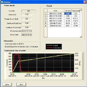
The Cathodic Protection Station measures the following parameters:

  • Ip – structure polarization current.
  • Uak – anode – structure voltage.
  • Eon – structure switching potential.
  • Eoff – structure shutdown potential.
  • Uac_on – Effective value of AC interference signals occurring on the structure.
  • Uac_off – Effective value of AC interference signals occurring on the structure.
  • E(t) – Measurement of the time course of the structure potential. “Oscilloscope” mode

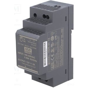
The SOLLICH 2003 CPS station requires a DC power supply with parameters depending on the version.

  • version: 24-300 (Us = 12 … 28V; Ip_max = 300 mA)
  • version: 24-600 (Us = 12 … 28V; Ip_max = 600 mA)
  • version: 24-1000 (Us = 12 … 28V; Ip_max = 1000 mA

Features of the device

  1. Operation in
    • galvanostatic mode – forcing a constant protection current
    • potentiostatic mode – forcing a constant protection potential
  2. Diversity of functions allowing configuration for a wide range of applications
  3. Possibility of programmatic disconnection of the station
  4. Current and potential regulation
  5. Automatic measurements
  6. Built-in accurate and interference-resistant measurement systems
  7. Recording changes in the structure’s potential over time. “Oscilloscope” mode.
  8. Analog-digital implementation of regulation and control systems
  9. Alphanumeric LCD display visible in the dark
  10. Information on the current operating status, alarm signals
  11. Built-in external logical inputs enabling control of the station operation
  12. Built-in external logical outputs enabling control of the operation of other devices in the OK installation
  13. Registration of protection parameters and signal values ​​in non-volatile memory
  14. High energy efficiency
  15. Remote reading of operating parameters
  16. Communication socket with external devices – RS485
  17. Support for Modbus protocol
  18. Made in accordance with the EMC directive
  19. Wide operating temperature range
  20. Simple installation on a DIN rail
  21. Simple start-up, easy operation

Technical Data

  1. TECHNICAL PARAMETERS
No.Electrical output parameters of the device:UnitMin valueMax valueNotes
1. Station power supply voltage  0V, UsV12 or 24Depending on the model
Minimum output current of the Station power supplyFor model: SOLLICH 2003 CPS / 24-300A0.800 Power supplies meeting the condition:24V-15W, or 12V-15W
For model: SOLLICH 2003 CPS / 24-600A1,250 Power supplies meeting the condition:24V-30W, or 12V-30W
For model: SOLLICH 2003 CPS / 24-1000A1,500 Power supplies meeting the condition:24V-50W, or 12V-30W
2.Protection output current – ​​Ip nominal current – ​​programmable valuemA0.5300Model 24-300
Ip current measurement inaccuracy%+mA2% +/- 0.3 mA
Protection output current – ​​Ip nominal current – ​​programmable valuemA1600Model 24-600
Current measurement inaccuracy Ip%+mA2% +/- 0.5 mA
Protection output current – ​​Ip nominal current – ​​programmable valuemA51000Model 24-1000
Current measurement inaccuracyIp%+mA2% +/- 2 mA
3.Potential programming rangeEp,at terminalsEo-KpV0-5 
4.Potential measurement rangeEp,at terminalsEo-KpV0+/-7V  
5.Potential measurement inaccuracyEpmV+%+/- 2mV  +/- 0.5% 
6.Range of measurement of the effective value of AC interference at terminals Eo-KpVrms07 Vac 
7.Potential measurement inaccuracy EpmV+%+/- 3 mV +/- 0.5% 
8.Overvoltage limitation of the reference electrode input circuit EoV+/- 30VImax=2A@ t=10/1000us pulse
9.Series input resistance of the overvoltage limitation circuitOhm10k 
10.Voltage measurement range U_a measured at output terminals Au-KuV0+Us – 4 
11.Voltage measurement inaccuracy U_aV+%+/- 0.2V +/-2% 
12.Overvoltage limitation of Eo reference electrode input circuitV+/- 33VImax=5.5A@ t=10/1000us pulse
13.Output resistance in series of the anode circuitOhm0.1 
14.Current consumption of the station without connected installation circuits OK:    
– for backlight on mA 105 112@ Us = 12 Vdc
– for backlight offmA8892@ Us = 12 Vdc
– for backlight onmA6973@ Us = 24 Vdc
– for backlight offmA5862@ Us = 24 Vdc
15.Interval of writes to non-volatile memorymin.120,000 
16.Maximum number of samples saved to non-volatile memoryresults196,000> 22 years for 1/60 min recording.
17Programmable sampling time interval to memory in “oscilloscope” modet0.1ms1000msts
Maximum number of samples saved in “oscilloscope” mode 3000 
Maximum waveform recording time in oscilloscope modet1,000 msFor ts= 0.1 ms
3,000,000 msFor ts= 1000 ms


  1. GENERAL PARAMETERS
No.General:UnitValue
1.dimensions width x height x depthmm70 x 90 x 65
2.weightkg.approx. 0.35
3.maximum ambient temperature at full load power°C-20 to +45
4.maximum ambient relative humidity%95


Additional products

offering additional options

Masz więcej pytań?

Zostaw email, odezwiemy się do Ciebie!