SOLLICH 2100 v.08 CPS
Cathodic Protection Station, Imax=2A; GPS synchronization, Modbus RTU

SOLLICH 2100 v.08 CPS Cathodic Protection Station, 2A

  • Ip – polarization current from 2mA to 2A
  • Stable operation with high interference from power grids
  • Cathodic protection station with built-in GPS interrupter.
  • Microprocessor-controlled station.
  • High energy efficiency.
  • IP64 tightness.
  • RS-485 Modbus RTU communication
  • Measurement accuracy 0.1%
  • Multiple operating modes
  • Operation in “Oscilloscope” mode
  • Intuitive operation
  • Large display

Application for cathodic protection:

  • various types of pipelines
  • steel structures
  • liquid and gas fuel tanks

The Cathodic Protection Station is prepared to cooperate with SCADA systems.

Version:

  • v. 30V-2A
SKU: 0-1-1 Categories: ,

Documentation

and technical data

Description

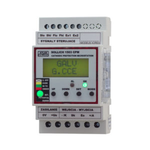
The SOLLICH 2100 v.08 CPS Cathodic Protection Station is designed for cathodic protection of metal structures built on a large area, on its surface, in the ground, water, with very good insulation in relation to the ground. In particular, these are all types of pipelines and gas pipelines.

The Cathodic Protection Station works in a three-electrode system with a reference electrode or in a two-electrode system without this electrode. The -/K cathode and the Ku terminal are connected to the protected structure.

The stations have built-in current interrupter keys and interruption synchronization systems with the GPS signal. This allows them to be used in synchronous measurements using the interruption of the polarization current, without the need to use external devices.

The OK station allows the implementation of the described task automatically by adjusting the operating parameters so as to force the set value of the current or potential. The device has the ability to manually and remotely change the operating mode and parameters.

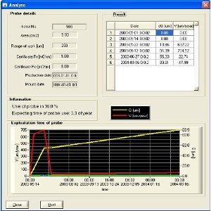
The station can record the results of the Eo potential measurement in the “oscilloscope” mode. This allows viewing the value of the structure’s potential and the shape and level of interference occurring on it.

The Cathodic Protection Station measures the following parameters:

  • Ip – structure polarization current.
  • Uak – anode – structure voltage.
  • Eon – structure’s on potential.
  • Eoff – structure’s off potential.
  • Uac_on – RMS value of AC interference signals occurring on the structure.
  • Uac_off – RMS value of AC interference signals occurring on the structure.
  • E(t) – Measurement of the time course of the structure’s potential.

Device features

  • Main features of the device:
    • Polarizer operating modes: Galvanostat, potentiostat and voltage power supply,
    • Operating modes and functions allowing configuration in a wide range of applications,
    • Programmable setting and precise measurements of current, potential and voltage,
    • Wide range of polarization current adjustment,
    • For each station in the SOLLICH 2100 v.08 CPS version, current adjustment range from 2mA to 2A,
    • The device has built-in mechanisms for stable operation in the presence of voltage
    • Very high resistance to interference with alternating currents induced on the structure,
    • A version that accepts interference with an ac signal up to 30 Vpp is possible,
    • Large LCD display with backlight, information about the current operating status,
    • High energy efficiency,
  • The station has a built-in Current Interrupter controlled by the GPS signal, does not require an additional RS 232 input,
  • Programmable calendar and schedule of intermittent operation,
  • GPS antenna included,
  • Possibility of clocking with two values ​​of polarization current,
  • The device is equipped with additional outputs and inputs enabling control of external devices,
  • RS connector 485 with Modbus protocol support for communication with external devices,
  • Power supply from 230V-50/60Hz mains,
  • Possibility of power supply from 12/24 Vdc battery – special version

Technical data

No.Electrical output parameters of the device:UnitMin valueMax valueNotes
1. Station output voltage  UaV030 / 24*)*) Depending on the version power supply
Protection output current – ​​Ip nominal current – ​​programmable valuemA22000Model 2A
Current measurement inaccuracy Ip%+mA1% +/- 1 mA
4.Programming range of Ep potential on terminals Eo-Kp Eo-KpV-10+10 
6.Potential measurement inaccuracy EpmV+%+/- 2mV  +/- 0.5% 
7.RMS measurement range of AC interference signal at Eo-Kp terminalsVrms015
10
Power supply version Us=30V
Power supply version Us=24V
8.Overvoltage limitation of the reference electrode input circuit EoV+/- 30VImax=2A@ t=10/1000us pulse
9.Input series resistance of the overvoltage limiting circuitOhm10k 
10.Voltage measurement range U_a measured at the output terminals Au-KuV050 
11.Voltage measurement inaccuracy U_aV+%+/- 0.2V +/-2% 
12.Overvoltage limitation of the anode output circuit +/AV+/- 100VImax=5.5A@ t=10/1000us pulse
13.Series output resistance of the anode circuitOhm0 
 14.Interval of writes to non-volatile memorymin.120,000 
15.Maximum number of samples saved to non-volatile memoryresults196,000> 22 years for 1/60 min recording.
16.Programmable sampling time interval to memory in “oscilloscope” modet0.1ms1000msts
Maximum number of samples saved in “oscilloscope” mode 3000 
Maximum waveform recording time in oscilloscope modet1,000 ms
3,000,000 ms
For ts= 0.1 ms
For ts= 1000 ms
17.Fuse type: 5×20 T250V Station anode circuit protectionAWTAT 2.5 A/250VModel 30/2000
18.Housing dimensions W x H x D for v.08mm260 x 240 x 130With cable glands
19.Housing material Polycarbonate 
20.Mounting method DIN 35 railmmDIN 35 
21.Power consumption from the mains 230V/50HzWMax.100 
22.Operating temperature rangeºC -20 … +40 
23.Maximum air humidity%95 

Additional products

offering additional options

Masz więcej pytań?

Zostaw email, odezwiemy się do Ciebie!