Description
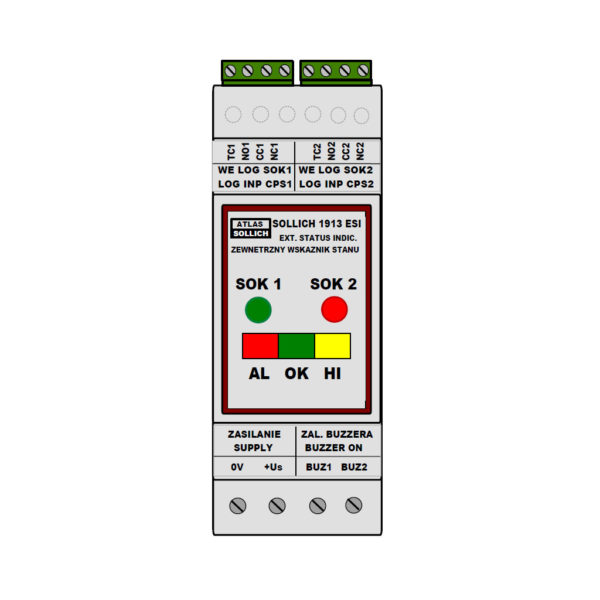
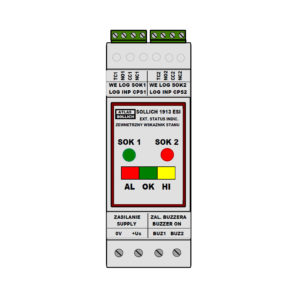
SOLLICH 1913 SI – EXTERNAL STATUS INDICATOR, serves as an indicator located outside the installation box – a light and / or acoustic indicator – of the correct polarity of the structure, implemented by a cathodic protection system based on the cathodic protection SOLLICH 1507 CPCS station and the installed SOLLICH 1912 SI Status Indicator.
The range of proper protection is indicated by the lighting color of the LED diode.
The SOLLICH 1912 SI status indicator signals the exceeding of the correct polarity range by the OK station and generates galvanically separated logic signals.
These signals can be sent by a 3-wire installation over long distances, without disturbing the CP station operation.
Connected at the other end of the 3-wire system, the SOLLICH 1913 ESI External Status Indicator receives these signals and converts them into light and acoustic information.
The External Status Indicator SOLLICH 1913 ESI enables the following signaling modes to be set:
- light signaling with a LED diode, illuminating:
- 2-color, green or red – Ep within or outside the scope of correct protection, respectively,
- Red – the potential is outside the range of correct protection (too low or too high)
- Green – the potential is within the set range of the correct protection potential
- o 3-color, green, or red, or yellow – Ep in the range, or below the range, or above the range of correct protection, respectively.
- Red – The protection potential is too low
- Green – the protection potential is within the set limits
- Yellow – The protection potential is too high.
- the acoustic signaling with the internal buzzer is on, if the jumper is on the terminals BUZ1 and BUZ2.
- Lack of a jumper on terminals BUZ1 and BUZ2 disables the acoustic signaling.
- 2-color, green or red – Ep within or outside the scope of correct protection, respectively,
The device is powered at the terminals 0V and + Us from the 12Vdc direct current power supply

