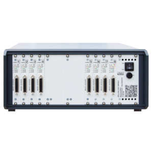
| 1. | ICDU Channels |
| 1.1. | CH 1 – STARTER channel | Channel triggering the measurement process 24V-2A | |
| 1.2. | CH 2 – SOURCE 1 | 50V-20A programmable power supply channel | |
| 1.3 | CH 3 – SOURCE 2 | 50V-20A programmable power supply channel | |
| 1.4 | CH 4 – MEASUREMENT | Measurement Channel | |
| 1.5 | CH 5 – LOAD 1 | Programmable load channel 50V-20A | |
| 1.6 | CH 6 – LOAD 2 | Programmable load channel 50V-20A | |
| 1.7 | CH 7 – LOAD 3 | Programmable load channel 50V-20A | |
| 1.8 | CH 8 – LOAD 4 | Programmable load channel 50V-20A | |
| 1.9 | CH 9 – LOAD 300 | Programmable load channel 300V-0.2A | |
| 2. | CH 1 – STARTER channel |
| 2.1 | Mode of operation: | CV & CC |
| | Parameter | Min value | Max value | Unit |
| 2.2 | U_out output voltage setting range | 0.1 | 24 | V |
| 2.3 | Resolution of U_out setting | 16 | bit |
| 2.4 | U_out voltage value setting inaccuracy | < +/- 10 | mV |
| 2.5 | U_out measurement range | 25 | V |
| 2.6 | U_out voltage value measurement resolution | 16 | bits |
| 2.7 | U_out voltage value measurement inaccuracy | < 10 | mV |
| 2.8 | I_out current setting range | 0.001 | 2 | A |
| 2.9 | Programming inaccuracy of the current I_out | < +/- 1 | mA |
| 2.10 | Resolution of the I_out setting | 16 | bit |
| 2.11 | I_out measurement ranges | 2.5 | A |
| 2.12 | I_out current value measurement resolution | 16 | bits |
| 2.13 | I_out current value measurement inaccuracy | < 10 | mV |
| 2.14 | Resolution for setting U_out and I_out values | 1 | 10 | ms |
| 2.15 | Frequency of U_out and I_out measurements | 1 | – | ms |
| 2.16 | Voltage measurement input impedance | 100 | – | kOhm |
| 2.17 | Channel protection on the connection panel | 2 x WTAT 3.15A | |
| | | | |
| 3. | CH 2 and CH 3 – SOURCE channels |
| 3.1 | Mode of operation: | CV & CC |
| | Parameter | Min value | Max value | Unit |
| 3.2 | U_out output voltage setting range | 0.1 | 50 | V |
| 3.3 | Resolution of U_out setting | 16 | bit |
| 3.4 | U_out voltage value setting inaccuracy | < +/- 10 | mV |
| 3.5 | U_out measurement ranges | 3; 6; 12; 25; 50 | V |
| 3.6 | U_out voltage value measurement resolution | 16 | bits |
| 3.7 | U_out voltage value measurement inaccuracy | < 10 | mV |
| 3.8 | I_out current setting range | 0.001 | 20 | A |
| 3.9 | Programming inaccuracy of the current I_out | < +/- 10 | mA |
| 3.10 | Resolution of the I_out setting | 16 | bit |
| 3.11 | I_out measurement ranges | 1.25; 2.5; 5; 10; 20 | A |
| 3.12 | I_out current value measurement resolution | 16 | bits |
| 3.13 | I_out current value measurement inaccuracy | < 10 | mV |
| 3.14 | Resolution for setting U_out and I_out values | 1 | 10 | ms |
| 3.15 | Frequency of U_out and I_out measurements | 1 | – | ms |
| 3.16 | Voltage measurement input impedance | 100 | – | kOhm |
| 3.17 | Channel protection on the connection panel | 2 x T 20 A | |
| 4. | CH 4 – MEASUREMENT channel |
| 4.1 | Mode of operation: | Measure U & And |
| | Parameter | Min value | Max value | Unit |
| 4.2 | Voltage U ranges | 3; 6; 12; 25; 50 | V |
| 4.3 | Resolution of voltage U measurement | 16 | bits |
| 4.4 | Inaccuracy of voltage U measurement | < 10 | mV |
| 4.5 | Ranges of current I measurement | 1.25; 2.5; 5; 10; 20 | A |
| 4.6 | Resolution of current I measurement | 16 | bits |
| 4.7 | Inaccuracy of current I measurement | < 10 | mV |
| 4.8 | Frequency of U and I measurements | 1 | – | ms |
| 4.9 | Voltage measurement input impedance | 100 | – | kOhm |
| 4.10 | Channel protection on the connection panel | 2 x WTAT 1A | |
| 5. | CH 5, CH 6, CH 7, CH 8 – LOAD 50V channels |
| 5.1 | Mode of operation: | I = const; R = const; P = const |
| 5 | Parameter | Min value | Max value | Unit |
| 5.2 | Load current setting range I | 0.001 | 20 | A |
| 5.3 | Programming inaccuracy of current I | < +/- 10 | mA |
| 5.4 | Resolution for setting I | 16 | bit |
| 5.5 | Measurement ranges I | 1.25; 2.5; 5; 10; 20 | A |
| 5.6 | Resolution of current I measurement | 16 | bits |
| 5.7 | Inaccuracy of current I measurement | < 10 | mV |
| 5.8 | Load resistance R range | 0.25 | 50 k | Ω |
| 5.9 | Resolution for setting the load resistance R | 16 | bit |
| 5.10 | Inaccuracy of load resistance R setting | < +/- 0.1 | % |
| 5.11 | Load power setting range P | 0.25 | 200 | W |
| 5.12 | Resolution of load power setting P | 16 | bit |
| 5.13 | Inaccuracy of load power P setting | < +/- 0.1 | % |
| 5.14 | Resolution for setting I, R, P values | 1 | 10 | ms |
| 5.15 | Frequency of measuring I, R, P values | 1 | – | ms |
| 5.16 | Channel protection on the connection panel | 2 x T 20 A | |
| 5.17 | | | |
| 6. | CH 9 – LOAD 300V channel |
| 6.1 | Mode of operation: | I = const; R = const; P = const |
| | Parameter | Min value | Max value | Unit |
| 6.2 | Load current setting range I | 0.001 | 0.2 | A |
| 6.3 | Programming inaccuracy of current I | < +/- 1 | mA |
| 6.4 | Resolution for setting I | 16 | bit |
| 6.5 | Measurement ranges I | 1 | A |
| 6.6 | Resolution of current I measurement | 16 | bits |
| 6.7 | Inaccuracy of current I measurement | < 20 | mV |
| 6.8 | Load resistance R range | 1 | 1000 | kΩ |
| 6.9 | Resolution for setting the load resistance R | 16 | bit |
| 6.10 | Inaccuracy of load resistance R setting | < +/- 0.2 | % |
| 6.11 | Load power setting range P | 0.1 | 20 | W |
| 6.12 | Resolution of load power setting P | 16 | bit |
| 6.13 | Inaccuracy of load power P setting | < +/- 0.2 | % |
| 6.14 | Resolution for setting I, R, P values | 1 | 10 | ms |
| 6.15 | Frequency of measuring I, R, P values | 1 | – | ms |
| 6.16 | Channel protection on the connection panel | 2 x T 1 A | |
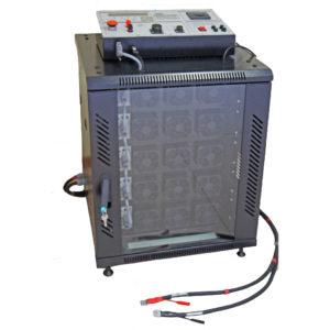
| 7 | General |
| 7.1. | Power | 230 +/- 10% 48 – 60 | V Hz |
| 7.2. | Max power consumption | 2400 | VA |
| 7.3. | 230 V line protection | 16 | A |
| 7.4. | Metal enclosure – W x D x H | 600 x 600 x 1600 | mm |
| 7.5. | Weight | ok. 160 | kg |
| 7.6. | Lab bench – S x D x H | 1200 x 800 x 1400 | mm |
| 7.7 | Weight | ok. 33 | kg |